Monday, September 7, 2009

Type Computer Network

Networks are all about sharing resources of computers, servers, printers, scanners etc to each other. There are two different types with which network between computers can be formed. Networking formation completely depends on the requirement of the organization scale and usability. We should always study requirements and needs before we decide to choose any type of network. Picking wrong set of options can cost you waste of money, time and resources. Two types of networks are Peer to Peer networking also known to be p2p, the other one is Client and Server networks.


Peer to peer (p2p)

P2p networking type is most commonly used computer networks. This type of network is very cost effective but supports lesser number of computers in network. Ten to fifteen computers can be connected to each other using p2p networking model without problem, more number of computers often create problems. All computers possesses same status within the network and no computer control any other computer but it self, this network does not have server to control and monitor. Security level is not towards higher side and each work station it self is responsible for security. Using p2p models files can be shared among computers. Files like, videos, audios, pictures, spreadsheets and all digital media can be sent or received with in the network. Printers, scanners and internet can be shared with in all computers. Below is the picture showing three computers connected to each other with hub and switch. All computers are connected to hub through Network adaptor card using Cable and hub or switch is connected to internet to pass it on to connected computers.. You can see there is no server involved in this diagram but all individual computers are connecting to hub forming P2P network.
Limitation of P2P networking model

Before deciding to implement P2P model one must know the limitations of this type. Getting to know later can be frustrating big time. It would highly be recommended to get your organizational people site together and discuss the needs. Peer to Peer looks very simple, quite cost effective and attractive, yet it can keep progress very limited.


Peer-To-Peer networks are designed for limited number computers, it will start creating issues when exceed 15 number of computers
High security levels can not be achieved using p2p networks, so if organization have concerns with security p2p will not be that great.
Organizational growth will outgrow p2p networks; it will not support growing number of computers when increased above fifteen.
Regular training is required for computer users of p2p network. p2p network is control by computers and computers are controlled by human, small mistake by one of the user can hold the work for other users on same p2p network.

Client Server Network Model

Choosing right kind of networking model is very important for organization. If you are using lesser number of computer and do not see any need to increase the numbers of computers to more than 15 then you are fine with peer to peer networking model, but if you are bigger organization or seeing growth in network, client and server model is designed for it.


The difference in p2p and client server model is that p2p does not have any device or computer that controls computers on network whereas; client / server model has one dedicated computer which is called server. It is called dedicated server. All computers are connected to hub and hub is connected to dedicated server. Server is responsible to perform according to the request sent to it by clients. For example server can act as print server, if client request a print of document server will send print command to printer and it will be printed. Same way all the files are stored on the server and not on client computer, same client can retrieve data by using any other computer on the same network. This concept is known as centralization, this enables server to keep profile of users, data, and software etc completely in tacked and organized.

Normal computer can also be configured as server and it should be alright and perform server tasks efficiently, but if network growth is on seen and many computers are required to attach to network that’s where we might need proper server to take over the network.

You can see in diagram below. All the workstations (Clients) are attached on server, some times there is hub involved but in this case it is just clients and server.
Features of Server

Servers are powerful machines when they are compared to normal desktop computers. They are meant to provide strength to computing power within the entire network. Controlling developed network can only be done by dedicated servers as they have higher specifications to support network. Servers can have better processing speed with multiple p\rocessors capability available. Server machine have higher RAM to load and execute software with ease. They have more advance network cards installed for faster data transfer. Hard drives are way bigger to store the data for entire clients. Hardware can be plugged in and plugged out while server is on, this helps network stable, and hardware like hard disk can be removed and attached accordingly.

Server Os

Operating systems are also specially designed for servers. Server Os have much more features file serving, print serving, backing up data, enhanced security features etc. There are few major Server Os which are used commonly in servers, Windows server NT. 2000 , 2003,Linux and Novell NetWare. Windows server 2003 is more powerful and enhanced for much higher security levels, Linux servers provide the maximum security to networks.

Network Topologies

Network topology is one of the very important topics to learn when it comes to build up computer network. There are many Network Topologies on which network administrator decide to build the network on. Topology is basically defined as layout or design of network, and computers are connected using the design of the topology. These topologies can be either physical or logical design. Physical topology refers to physical design of network which includes devices, cables, location and installation of network where as in logical topology it is the amount of data to be transferred with in the network as apposed in its design.

There are five different Networking Topologies :
a) Bus b) Star c) Ringd) Mesh e) Tree.
When networks are design using multiple topologies it is called Hybrid Networks, this concept is usually utilized in complex networks were larger number of computer clients are required.

Bus Topology

Bus topology is one the easiest topologies to install, it does not require lots of cabling. There are two most popular Ethernet cable types which are used in this topology they are 10Base-2 and 10BaseT. Bus topology based networks works with very limited devices. It performs fine as long as computer count remain with in 12 – 15, problems occurs when number of computer increases.Bus topology uses one common cable (backbone) to connect all devices in the network in linear shape. Network interface cards of all network devices are attached to single communication medium backbone cable. When any computer sends out message in the network it is broadcasted in the entire network but only intended computer accepts the message and process it. Bus topology provide simplicity to the network, however there is big disadvantage of this topology, if main single network cable some how gets damaged, it will shut down the entire network no computer will run on network and no communication can be made among computers until backbone cable is replaced.

Ring Topology

Ring topology is one of the old ways of building computer network design and it is pretty much obsolete. FDDI, SONET or Token Ring technologies are used to build ring technology. It is not widely popular in terms of usability but incase if you find it any where it will mostly be in schools or office buildings. In ring network topology computers and other networking devices are attached to each other in such a way that they have devices adjacent to each other (Left and right side). All messages are travelled in the same directory either clockwise or anticlockwise. In case of failure of any device or cable the whole network will be down and communication will not be possible.

Star Topology

This is the most commonly used network topology design you will come across in LAN computer networks. In Star, all computers are connected to central device called hub, router or switches using Unshielded Twisted Pair (UTP) or Shielded Twisted Pair cables.In star topology, we require more connecting devices like routers, cables unlike in bus topology where entire network is supported by single backbone. The most practical point of Star topology success is that the entire network does not go down incase of failure of a computer or cable or device, it will only affect the computer whose wire failed rest of the network will be working fine. However, incase of failure of central communication device such as Hub, Router or Switch the entire network will collapse.

Tree Topology

Just as name suggest, the network design is little confusing and complex to understand at first but if we have better understanding of Star and Bus topologies then Tree is very simple. Tree topology is basically the mixture of many Star topology designs connected together using bus topology. Devices like Hub can be directly connected to Tree bus and each hub performs as root of a tree of the network devices. Tree topology is very dynamic in nature and it holds potential of expandability of networks far better than other topologies like Bus and Star.

Mesh Topology

Mesh topology is designed over the concept of routing. Basically it uses router to choose the shortest distance for the destination. In topologies like star, bus etc, message is broadcasted to entire network and only intended computer accepts the message, but in mesh the message is only sent to the destination computer which finds its route it self with the help of router. Internet is based on mesh topology. Routers plays important role in mesh topology, routers are responsible to route the message to its destination address or computer. When every device is connected to every other device it is known as full mesh topology and if every device is connected indirectly to each other then it is called partial mesh topology.

Friday, September 4, 2009

The Cisco Three-Layered Hierarchical Model

Cisco has defined a hierarchical model known as the hierarchical internetworking model. This model simplifies the task of building a reliable, scalable, and less expensive hierarchical internetwork because rather than focusing on packet construction, it focuses on the three functional areas, or layers, of your network:
Core layer: This layer is considered the backbone of the network and includes the high-end switches and high-speed cables such as fiber cables. This layer of the network does not route traffic at the LAN. In addition, no packet manipulation is done by devices in this layer. Rather, this layer is concerned with speed and ensures reliable delivery of packets.
Distribution layer: This layer includes LAN-based routers and layer 3 switches. This layer ensures that packets are properly routed between subnets and VLANs in your enterprise. This layer is also called the Workgroup layer.

Access layer: This layer includes hubs and switches. This layer is also called the desktop layer because it focuses on connecting client nodes, such as workstations to the network. This layer ensures that packets are delivered to end user computers.

Switching & Bridging

The Switch

A switch is a layer 2 network device that forwards frames using MAC addresses in the header of frames. It is used to improve network performance by:-
• segmenting the network and creating separate collision domains.
• reducing competition for bandwidth.
In a switch frame forwarding is handled by specialized hardware called "Application Specific Integrated Circuit" (ASIC). ASIC technology allows a silicon chip to be programmed to perform specific functions much faster than that of a chip programmed by software.


Steps of Switch Functioning

Learning When switch starts, the MAC address table has no entry. When a node transmits data on its wire the MAC address of the node is learned by Switch Port connected to that node. In this way all the MAC addresses are learned by respective ports and these entries remain in the cache for a specific time. If during this specific time no new frame arrives from a node MAC address entry for that node is dropped from cache.
Forwarding & Filtering
When a MAC address for a port is learnt, packets addressed to that MAC address are forwarded only to the port associated with it, using one of the Switching Methods.
Loop Avoidance
Switches and Bridges use Spanning Tree Protocol (STP), specified by IEEE 802.1d, to prevent

Switching Methods

Store & Forward: In this method complete frame is received by the switch. CRC, source address and destination address are checked. This method has following features:-
• Highest latency (delay in forwarding of frame) but may vary depending upon the length of frame.
• Highest error checking.
• Lowest frame forwarding speed.
Catalyst 500 switch uses this method.

Cut Through: In this method forwarding starts as soon as destination address of the frame is received in header. Also known as WIRE SPEED. This method has following features:-
• Lowest latency.
• Lowest error checking.
• Highest frame forwarding speed.
Fragment Free (Modified Cut Through): In this method forwarding starts as soon as first 64 bytes of the frame are received as fragmentation occurs usually in first 64 bytes. This method has following features:-
• Latency approx 60m Sec.
• Sufficient error checking.
• Moderate frame forwarding speed.

The Bridge

It is a layer 2 device used to connect different network types or networks of the same type. Packets having destination address on the same network segment are dropped. Bridges use "Store and Forward" method to inspect the whole packet.
Advantages: Using a bridge to segment network can provide:-
• Reliability.
• Manageability.
• Scalability.

Disadvantages:
• A bridge cannot filter out broadcast traffic.
• It introduces 20 to 30 % latency.
• Only 2 networks can be linked with a bridge.

Thursday, September 3, 2009

IP Addressing and Subnetting

Understanding IP Addresses

An IP address is an address used to uniquely identify a device on an IP network. The address is made up of 32 binary bits which can be divisible into a network portion and host portion with the help of a subnet mask. The 32 binary bits are broken into four octets (1 octet = 8 bits). Each octet is converted to decimal and separated by a period (dot). For this reason, an IP address is said to be expressed in dotted decimal format (for example, 172.16.81.100). The value in each octet ranges from 0 to 255 decimal, or 00000000 - 11111111 binary.

Here is how binary octets convert to decimal: The right most bit, or least significant bit, of an octet holds a value of 20. The bit just to the left of that holds a value of 21. This continues until the left-most bit, or most significant bit, which holds a value of 27. So if all binary bits are a one, the decimal equivalent would be 255 as shown here:

    1  1  1  1 1 1 1 1
128 64 32 16 8 4 2 1 (128+64+32+16+8+4+2+1=255)

Here is a sample octet conversion when not all of the bits are set to 1.

  0  1 0 0 0 0 0 1
0 64 0 0 0 0 0 1 (0+64+0+0+0+0+0+1=65)

And this is sample shows an IP address represented in both binary and decimal.

        10.       1.      23.      19 (decimal)
00001010.00000001.00010111.00010011 (binary)

These octets are broken down to provide an addressing scheme that can accommodate large and small networks. There are five different classes of networks, A to E. This document focuses on addressing classes A to C, since classes D and E are reserved and discussion of them is beyond the scope of this document.

Note: Also note that the terms "Class A, Class B" and so on are used in this document to help facilitate the understanding of IP addressing and subnetting. These terms are rarely used in the industry anymore because of the introduction of classless interdomain routing (CIDR).

Given an IP address, its class can be determined from the three high-order bits. Figure 1 shows the significance in the three high order bits and the range of addresses that fall into each class. For informational purposes, Class D and Class E addresses are also shown.

3an.gif

In a Class A address, the first octet is the network portion, so the Class A example in Figure 1 has a major network address of 1.0.0.0 - 127.255.255.255. Octets 2, 3, and 4 (the next 24 bits) are for the network manager to divide into subnets and hosts as he/she sees fit. Class A addresses are used for networks that have more than 65,536 hosts (actually, up to 16777214 hosts!).

In a Class B address, the first two octets are the network portion, so the Class B example in Figure 1 has a major network address of 128.0.0.0 - 191.255.255.255. Octets 3 and 4 (16 bits) are for local subnets and hosts. Class B addresses are used for networks that have between 256 and 65534 hosts.

In a Class C address, the first three octets are the network portion. The Class C example in Figure 1 has a major network address of 192.0.0.0 - 233.255.255.255. Octet 4 (8 bits) is for local subnets and hosts - perfect for networks with less than 254 hosts.

Network Masks

A network mask helps you know which portion of the address identifies the network and which portion of the address identifies the node. Class A, B, and C networks have default masks, also known as natural masks, as shown here:

Class A: 255.0.0.0
Class B: 255.255.0.0
Class C: 255.255.255.0

An IP address on a Class A network that has not been subnetted would have an address/mask pair similar to: 8.20.15.1 255.0.0.0. To see how the mask helps you identify the network and node parts of the address, convert the address and mask to binary numbers.

8.20.15.1 = 00001000.00010100.00001111.00000001
255.0.0.0 = 11111111.00000000.00000000.00000000

Once you have the address and the mask represented in binary, then identifying the network and host ID is easier. Any address bits which have corresponding mask bits set to 1 represent the network ID. Any address bits that have corresponding mask bits set to 0 represent the node ID.

8.20.15.1 = 00001000.00010100.00001111.00000001
255.0.0.0 = 11111111.00000000.00000000.00000000
-----------------------------------
net id | host id

netid = 00001000 = 8
hostid = 00010100.00001111.00000001 = 20.15.1

Understanding Subnetting

Subnetting allows you to create multiple logical networks that exist within a single Class A, B, or C network. If you do not subnet, you are only able to use one network from your Class A, B, or C network, which is unrealistic.

Each data link on a network must have a unique network ID, with every node on that link being a member of the same network. If you break a major network (Class A, B, or C) into smaller subnetworks, it allows you to create a network of interconnecting subnetworks. Each data link on this network would then have a unique network/subnetwork ID. Any device, or gateway, connecting n networks/subnetworks has n distinct IP addresses, one for each network / subnetwork that it interconnects.

In order to subnet a network, extend the natural mask using some of the bits from the host ID portion of the address to create a subnetwork ID. For example, given a Class C network of 204.17.5.0 which has a natural mask of 255.255.255.0, you can create subnets in this manner:

204.17.5.0 -      11001100.00010001.00000101.00000000
255.255.255.224 - 11111111.11111111.11111111.11100000
--------------------------|sub|----

By extending the mask to be 255.255.255.224, you have taken three bits (indicated by "sub") from the original host portion of the address and used them to make subnets. With these three bits, it is possible to create eight subnets. With the remaining five host ID bits, each subnet can have up to 32 host addresses, 30 of which can actually be assigned to a device since host ids of all zeros or all ones are not allowed (it is very important to remember this). So, with this in mind, these subnets have been created.

204.17.5.0 255.255.255.224     host address range 1 to 30
204.17.5.32 255.255.255.224 host address range 33 to 62
204.17.5.64 255.255.255.224 host address range 65 to 94
204.17.5.96 255.255.255.224 host address range 97 to 126
204.17.5.128 255.255.255.224 host address range 129 to 158
204.17.5.160 255.255.255.224 host address range 161 to 190
204.17.5.192 255.255.255.224 host address range 193 to 222
204.17.5.224 255.255.255.224 host address range 225 to 254

Note: There are two ways to denote these masks. First, since you are using three bits more than the "natural" Class C mask, you can denote these addresses as having a 3-bit subnet mask. Or, secondly, the mask of 255.255.255.224 can also be denoted as /27 as there are 27 bits that are set in the mask. This second method is used with CIDR. Using this method, one of these networks can be described with the notation prefix/length. For example, 204.17.5.32/27 denotes the network 204.17.5.32 255.255.255.224. When appropriate the prefix/length notation is used to denote the mask throughout the rest of this document.

The network subnetting scheme in this section allows for eight subnets, and the network might appear as:

3b.gif

Notice that each of the routers in Figure 2 is attached to four subnetworks, one subnetwork is common to both routers. Also, each router has an IP address for each subnetwork to which it is attached. Each subnetwork could potentially support up to 30 host addresses.

This brings up an interesting point. The more host bits you use for a subnet mask, the more subnets you have available. However, the more subnets available, the less host addresses available per subnet. For example, a Class C network of 204.17.5.0 and a mask of 255.255.255.224 (/27) allows you to have eight subnets, each with 32 host addresses (30 of which could be assigned to devices). If you use a mask of 255.255.255.240 (/28), the break down is:

204.17.5.0 -      11001100.00010001.00000101.00000000
255.255.255.240 - 11111111.11111111.11111111.11110000
--------------------------|sub |---

Since you now have four bits to make subnets with, you only have four bits left for host addresses. So in this case you can have up to 16 subnets, each of which can have up to 16 host addresses (14 of which can be assigned to devices).

Take a look at how a Class B network might be subnetted. If you have network 172.16.0.0 ,then you know that its natural mask is 255.255.0.0 or 172.16.0.0/16. Extending the mask to anything beyond 255.255.0.0 means you are subnetting. You can quickly see that you have the ability to create a lot more subnets than with the Class C network. If you use a mask of 255.255.248.0 (/21), how many subnets and hosts per subnet does this allow for?

172.16.0.0  -   10101100.00010000.00000000.00000000
255.255.248.0 - 11111111.11111111.11111000.00000000
-----------------| sub |-----------

You are using five bits from the original host bits for subnets. This allows you to have 32 subnets (25). After using the five bits for subnetting, you are left with 11 bits for host addresses. This allows each subnet so have 2048 host addresses (211), 2046 of which could be assigned to devices.

Note: In the past, there were limitations to the use of a subnet 0 (all subnet bits are set to zero) and all ones subnet (all subnet bits set to one). Some devices would not allow the use of these subnets. Cisco Systems devices allow the use of these subnets when theip subnet zero command is configured.

Examples

Sample Exercise 1

Now that you have an understanding of subnetting, put this knowledge to use. In this example, you are given two address / mask combinations, written with the prefix/length notation, which have been assigned to two devices. Your task is to determine if these devices are on the same subnet or different subnets. You can do this by using the address and mask of each device to determine to which subnet each address belongs.

DeviceA: 172.16.17.30/20
DeviceB: 172.16.28.15/20

Determining the Subnet for DeviceA:

172.16.17.30  -   10101100.00010000.00010001.00011110
255.255.240.0 - 11111111.11111111.11110000.00000000
-----------------| sub|------------
subnet = 10101100.00010000.00010000.00000000 = 172.16.16.0

Looking at the address bits that have a corresponding mask bit set to one, and setting all the other address bits to zero (this is equivalent to performing a logical "AND" between the mask and address), shows you to which subnet this address belongs. In this case, DeviceA belongs to subnet 172.16.16.0.

Determining the Subnet for DeviceB:

172.16.28.15  -   10101100.00010000.00011100.00001111
255.255.240.0 - 11111111.11111111.11110000.00000000
-----------------| sub|------------
subnet = 10101100.00010000.00010000.00000000 = 172.16.16.0

From these determinations, DeviceA and DeviceB have addresses that are part of the same subnet.

Sample Exercise 2

Given the Class C network of 204.15.5.0/24, subnet the network in order to create the network in Figure 3 with the host requirements shown.

3c.gif

Looking at the network shown in Figure 3, you can see that you are required to create five subnets. The largest subnet must support 28 host addresses. Is this possible with a Class C network? and if so, then how?

You can start by looking at the subnet requirement. In order to create the five needed subnets you would need to use three bits from the Class C host bits. Two bits would only allow you four subnets (22).

Since you need three subnet bits, that leaves you with five bits for the host portion of the address. How many hosts does this support? 25 = 32 (30 usable). This meets the requirement.

Therefore you have determined that it is possible to create this network with a Class C network. An example of how you might assign the subnetworks is:

netA: 204.15.5.0/27      host address range 1 to 30
netB: 204.15.5.32/27 host address range 33 to 62
netC: 204.15.5.64/27 host address range 65 to 94
netD: 204.15.5.96/27 host address range 97 to 126
netE: 204.15.5.128/27 host address range 129 to 158


VLSM Example

In all of the previous examples of subnetting, notice that the same subnet mask was applied for all the subnets. This means that each subnet has the same number of available host addresses. You can need this in some cases, but, in most cases, having the same subnet mask for all subnets ends up wasting address space. For example, in the Sample Exercise 2 section, a class C network was split into eight equal-size subnets; however, each subnet did not utilize all available host addresses, which results in wasted address space. Figure 4 illustrates this wasted address space.

3d.gif

Figure 4 illustrates that of the subnets that are being used, NetA, NetC, and NetD have a lot of unused host address space. It is possible that this was a deliberate design accounting for future growth, but in many cases this is just wasted address space due to the fact that the same subnet mask is being used for all the subnets.

Variable Length Subnet Masks (VLSM) allows you to use different masks for each subnet, thereby using address space efficiently.

VLSM Example

Given the same network and requirements as in Sample Exercise 2 develop a subnetting scheme with the use of VLSM, given:

netA: must support 14 hosts
netB: must support 28 hosts
netC: must support 2 hosts
netD: must support 7 hosts
netE: must support 28 host

Determine what mask allows the required number of hosts.

netA: requires a /28 (255.255.255.240) mask to support 14 hosts
netB: requires a /27 (255.255.255.224) mask to support 28 hosts
netC: requires a /30 (255.255.255.252) mask to support 2 hosts
netD*: requires a /28 (255.255.255.240) mask to support 7 hosts
netE: requires a /27 (255.255.255.224) mask to support 28 hosts

* a /29 (255.255.255.248) would only allow 6 usable host addresses
therefore netD requires a /28 mask.

The easiest way to assign the subnets is to assign the largest first. For example, you can assign in this manner:

netB: 204.15.5.0/27  host address range 1 to 30
netE: 204.15.5.32/27 host address range 33 to 62
netA: 204.15.5.64/28 host address range 65 to 78
netD: 204.15.5.80/28 host address range 81 to 94
netC: 204.15.5.96/30 host address range 97 to 98

This can be graphically represented as shown in Figure 5:

3e.gif

Figure 5 illustrates how using VLSM helped save more than half of the address space.

CIDR

Classless Interdomain Routing (CIDR) was introduced to improve both address space utilization and routing scalability in the Internet. It was needed because of the rapid growth of the Internet and growth of the IP routing tables held in the Internet routers.

CIDR moves way from the traditional IP classes (Class A, Class B, Class C, and so on). In CIDR , an IP network is represented by a prefix, which is an IP address and some indication of the length of the mask. Length means the number of left-most contiguous mask bits that are set to one. So network 172.16.0.0 255.255.0.0 can be represented as 172.16.0.0/16. CIDR also depicts a more hierarchical Internet architecture, where each domain takes its IP addresses from a higher level. This allows for the summarization of the domains to be done at the higher level. For example, if an ISP owns network 172.16.0.0/16, then the ISP can offer 172.16.1.0/24, 172.16.2.0/24, and so on to customers. Yet, when advertising to other providers, the ISP only needs to advertise 172.16.0.0/16.

For more information on CIDR, see RFC 1518 leavingcisco.com and RFC 1519 leavingcisco.com.

Appendix

Sample Config

Routers A and B are connected via serial interface.

Router A

  hostname routera
!
ip routing
!
int e 0
ip address 172.16.50.1 255.255.255.0
!(subnet 50)
int e 1 ip address 172.16.55.1 255.255.255.0
!(subnet 55)
int t 0 ip address 172.16.60.1 255.255.255.0
!(subnet 60) int s 0
ip address 172.16.65.1 255.255.255.0 (subnet 65)
!S 0 connects to router B
router rip
network 172.16.0.0

Router B

  hostname routerb
!
ip routing
!
int e 0
ip address 192.1.10.200 255.255.255.240
!(subnet 192)
int e 1
ip address 192.1.10.66 255.255.255.240
!(subnet 64)
int s 0
ip address 172.16.65.2 (same subnet as router A's s 0)
!Int s 0 connects to router A
router rip
network 192.1.10.0
network 172.16.0.0

Host/Subnet Quantities Table

Class B                   Effective  Effective
# bits Mask Subnets Hosts
------- --------------- --------- ---------
1 255.255.128.0 2 32766
2 255.255.192.0 4 16382
3 255.255.224.0 8 8190
4 255.255.240.0 16 4094
5 255.255.248.0 32 2046
6 255.255.252.0 64 1022
7 255.255.254.0 128 510
8 255.255.255.0 256 254
9 255.255.255.128 512 126
10 255.255.255.192 1024 62
11 255.255.255.224 2048 30
12 255.255.255.240 4096 14
13 255.255.255.248 8192 6
14 255.255.255.252 16384 2

Class C Effective Effective
# bits Mask Subnets Hosts
------- --------------- --------- ---------
1 255.255.255.128 2 126
2 255.255.255.192 4 62
3 255.255.255.224 8 30
4 255.255.255.240 16 14
5 255.255.255.248 32 6
6 255.255.255.252 64 2

Wednesday, September 2, 2009

OSI Network Model Standard /layers

OSI Network Model Standard /layers

The OSI network model layers are arranged here from the lower levels starting with the physical (hardware) to the higher levels.

  1. Physical Layer - The actual hardware.
  2. Data Link Layer - Data transfer method (802x ethernet). Puts data in frames and ensures error free transmission. Also controls the timing of the network transmission. Adds frame type, address, and error control information. IEEE divided this layer into the two following sublayers.
    1. Logical Link control (LLC) - Maintains the Link between two computers by establishing Service Access Points (SAPs) which are a series of interface points. IEEE 802.2.
    2. Media Access Control (MAC) - Used to coordinate the sending of data between computers. The 802.3, 4, 5, and 12 standards apply to this layer. If you hear someone talking about the MAC address of a network card, they are referring to the hardware address of the card.
  3. Network Layer - IP network protocol. Routes messages using the best path available.
  4. Transport Layer - TCP, UDP. Ensures properly sequenced and error free transmission.
  5. Session Layer - The user's interface to the network. Determines when the session is begun or opened, how long it is used, and when it is closed. Controls the transmission of data during the session. Supports security and name lookup enabling computers to locate each other.
  6. Presentation Layer - ASCII or EBCDEC data syntax. Makes the type of data transparent to the layers around it. Used to translate date to computer specific format such as byte ordering. It may include compression. It prepares the data, either for the network or the application depending on the direction it is going.
  7. Application Layer - Provides services software applications need. Provides the ability for user applications to interact with the network.

Many protocol stacks overlap the borders of the seven layer model by operating at multiple layers of the model. File Transport Protocol (FTP) and telnet both work at the application, presentation, and the session layers.


Windows Troubleshooting

How to fix svchost.exe errors and problems with high CPU usage


SVCHOST.EXE is one of those mysterious processes that constantly runs in Windows and is utterly essential, yet you never know exactly what it is doing. So what is SVCHOST.EXE? Identifying the actual services and programs that are running inside each SVCHOST.EXE process is a task well worth knowing, especially when the process eats up 99 or 100 percent of your CPU!

So before we dive into solutions, let’s get a deeper understanding of what this process actually does and how you can go about fixing some of the problems that might occur. Firstly, svchost stands for “service host” and it does exactly what as the name suggest: helps to “host” services. A service in Windows is simply a program in the operating system that does a particular and runs in the background at all times when your computer is on, even if you are not logged in.

Most programs that you are familiar with run as stand-alone executables, such .EXEs. However, most services are implemented in the form of DLLs, which cannot run on their own. Hence, svchost loads those DLLs and runs them itself. That’s why when you open the Windows Task Manager, you’ll see a bunch of svchost.exe processes running. If you want more info on the Task Manger, check out my articles on understanding the Task Manager.

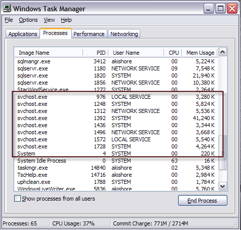
svchost

You’ll notice that there are currently eight svchost processes running on my computer, all using up various amounts of memory and running under different user names. So let’s say one of them is running at an excessively high CPU usage of 100 percent, how can we identify the actual application running?

There are actually two ways to go about this: doing it all manually using the command prompt and Services tool or by using a third party application. I’m going to mention both here in case one does not work for you.

Identify svchost.exe processes using command prompt (hard way)

1. First, go ahead and click on Start and then Run and type in CMD and click OK

command prompt

2. Type in the following into the command window and press Enter

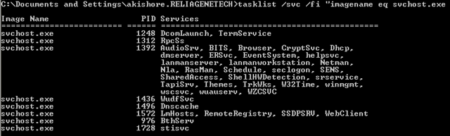
tasklist /svc /fi “imagename eq svchost.exe

You should get an output as shown below with the name, PID, and service description

svchost process

You’ll now see each svchost process along with it’s unique ID number and the services it is responsible for running. However, these names are still very cryptic and are all short hand names. In order to get some more useful information about the process, we can use the Services browser in Windows.

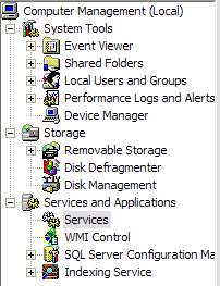
3. Right-click on My Computer, choose Manage. On the resulting screen, choose Computer Management and then choose Services and Applications. Finally, choose Services.

services

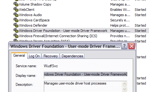
4. Now try to match the cryptic Windows service name with the easily readable names in the Services tab. This is a little and can take some time because if you take the process with ID 1436 and it’s name WudfSvc, you have to try to find it in the list. If you double-click on one the service names, you’ll see their cryptic name also, so that’s how you can match them up. In my case, I guessed that the W means the process starts with Windows… and opened them until I saw a match.

services1

As you can see, the Windows Driver Foundation service is actually called WudfSvc also!

Use Process Explorer to find programs running as svchost.exe (easy way)

If you found to be too difficult, there is a much easier way! Check out the Process Explorer tool from Microsoft (originally from SysInternals). The tool is completely free and gives you detailed information for each process currently running.

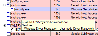
Once you download it, just run the exe file as it does not have to be installed. Hover your mouse over the svchost process and you’ll get a popup showing you which service is running under that process.

windows services

Fixing SVCHOST high CPU usage

Now that you have figured out exactly which process is eating up all of your CPU, we can address how to fix it. If you have found that the process is not a Windows process, such as Windows Update or Windows Firewall, etc, then simply kill the process and uninstall the program.

However, most of the time that this problem occurs, it has something to do with a Windows process. The best solution in this case is to install all of the latest updates from Microsoft’s web site. If you’re not able to do so normally in Windows, try restarting the computer in safe mode and try it again.

Also, if you can get to the Services tab like we did above, go ahead and right-click on the service and choose Disable. Even if it’s Windows Update or the Firewall, don’t worry, you can re-enable it later. Then restart the computer and go to Microsoft’s web site and manually get the updates. Re-enable the service and restart the computer again and hopefully things are working!

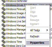
In order to disable a service in Windows, right-click on it from the Services tab and choose Properties.

disable services

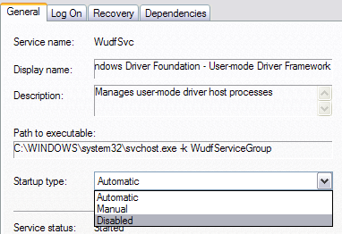
Next choose Disabled from the Startup type combo box located in the middle of the dialog box:

disable service

I have gone through this process a couple of times and it’s worked for me. So again, it’s disable the service, restart computer, install updates manually, re-enable service, and then restart computer again.